
Finding HMAS Sydney (II)
Survey Operations
The following is an excerpt from Section 2.0 of the Final Report.
Survey operations for the search for the Sydney and Kormoran were undertaken between and on board the survey vessel Geosounder.
The survey was conducted in two phases:
- Phase 1: Deep-water side scan sonar survey for initial wreck location
- Phase 2: ROV inspection and confirmation of wrecks once located
As the wreck sites are designated protected zones under Section 15 of the Historic Shipwrecks Act 1976 a permit to re-enter the sites with the ROV spread was required. A permit application was forwarded to the Department for the Environment, Water, Heritage and the Arts on the and permission for one month’s entry was granted on . Designated wreck protection zone coordinates were determined from the side scan sonar data as shown in Tables 2-1 and 2-2.
| Corner | Latitude (S) | Longitude (E) |
|---|---|---|
| NW Corner | 26° 14' 25.9" | 111° 12' 40.1" |
| NE Corner | 26° 14' 25.9" | 111° 13' 00.5" |
| SW Corner | 26° 14' 52.4" | 111° 12' 40.1" |
| SE Corner | 26° 14' 52.4" | 111° 13' 00.5" |
| Corner | Latitude (S) | Longitude (E) |
|---|---|---|
| NW Corner | 26° 05' 17.5" | 111° 03' 52.7" |
| NE Corner | 26° 05' 17.5" | 111° 04' 51.2" |
| SW Corner | 26° 06' 11.0" | 111° 03' 52.7" |
| SE Corner | 26° 06' 11.0" | 111° 04' 51.2" |
Side Scan Sonar Survey Phase
The following is an excerpt from Section 2.1 of the Final Report.
The W&A deep-water sonar winches and DOF’s ROV were mobilised in Singapore prior to the survey vessel Geosounder sailing to Geraldton on the . Mobilisation of the remaining vessel crew, DOF survey equipment, remaining W&A deep-water side scan sonar equipment, all survey personnel and client representatives was undertaken in Geraldton between and .
The side scan sonar survey was conducted between and using W&A’s SM-30 (30 kHz) and AMS-60 (60 kHz) deep-water sonar towfish, each with integrated 4.5 kHz sub-bottom profiler (for target detection within an acoustic ‘dead’ zone directly below the towfish). This period includes transit time between Geraldton, the location of sea trials off the Abrolhos Islands and the wreck search areas.
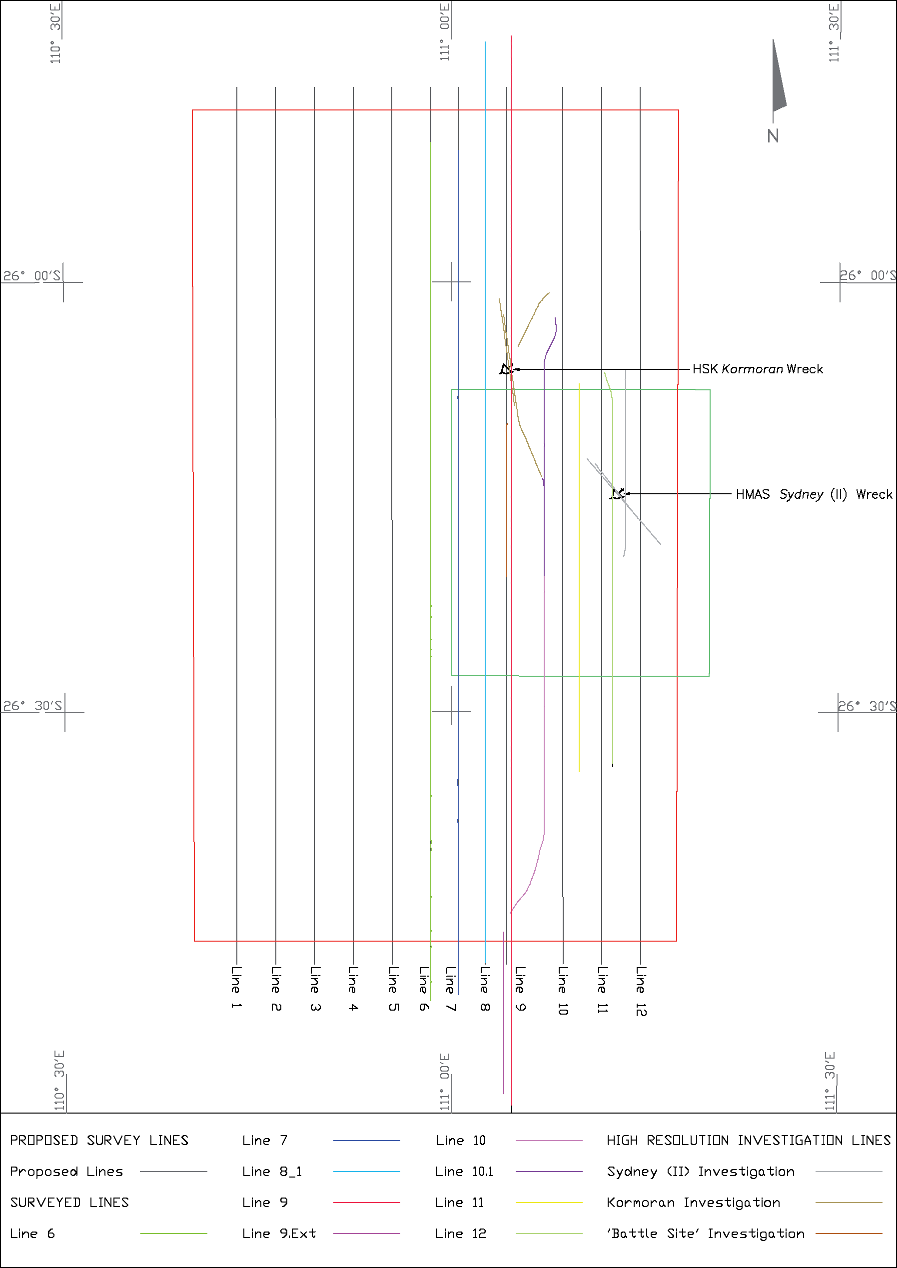
Proposed survey run-lines for the initial 69km x 108km search area comprised 12 parallel, north/south oriented primary lines, approximately 110km in length, at a nominal line spacing of 5,000m. This provided 100% sonar coverage at a sonar swath width of 6km. However, once sonar operations commenced it was determined that the acoustically strong echo from the sea-surface return resulted in data blanking of the outer sonar range data. Run-line spacing was reduced to between 3,400m and 3,700m to ensure 100% sonar coverage.
A vessel survey speed of two to three knots, and tow cable length of up to 9,000m, was required to maintain the sonar towfish height above the seabed of 5% to 7.5% of the sonar swath width. This ensured the required sonar ‘grazing’ angle for target detection. For example, a sonar swath setting of 6km required a towfish height of 350m above the seabed.
The scope of work did not require sonar towfish tracking therefore all survey lines were run in opposite directions wherever possible in order to minimise layback errors. A cable-counter was used to monitor the amount of cable paid out through the sheave block located on the A-frame at the stern of the vessel. An indicative towfish layback position along any point of the survey run-line could thus be determined.
All sonar data was acquired and processed using ISIS and SonarWiz sonar acquisition and processing software, and interpreted using W&A proprietary mapping software. Hard copy sonar data was output to an EPC 9800 graphic recorder. Final sonar target positioning was supported by processed, albeit, uncalibrated, multibeam echo-sounder (MBES) data acquired using DOF’s hull-mounted Simrad EM300.
The survey was initially concentrated around the central and eastern portion of the site and four (Lines 6 to 9) of the 12 north/south survey run-lines were completed before the Kormoran wreck site was located at AWT () on . A fifth and final north/south survey line, Line 10 (run in two parts), was only run as far north as the Kormoran wreck location.
Two high resolution sonar passes were undertaken using the SM-30 sonar towfish at swathes of 1.5km and 750m, and line headings of 352º and 172º respectively to investigate the Kormoran wreck site and establish a best-coordinated position.
Strong sonar targets south of the initial site were discounted as being geological in origin after one investigation sonar pass was carried out (see Line 9.Ext on Figure 1-2). In addition, one high resolution survey line was run using the SM-30 towfish on 750m swath setting and line heading of 180º to investigate what was thought to be the possible battle site. This site was found to be a number of large rock outcrops during the ROV inspection phase.
Two of the original 12 north/south run-lines (Lines 11 and 12) were then surveyed across the 37km x 37km Sydney survey area using the SM-30 sonar on a 6km swath setting before the Sydney wreck site was located at AWT () on .
Three high resolution survey lines were then run at swath widths of 3km, 1.5km and 750m and line headings of 180º, 319º and 139º respectively to further investigate the Sydney wreck site. The latter two lines were run parallel to the wreck’s hull.
The SM-30 sonar towfish was recovered upon completion of the high resolution survey lines. The higher resolution AMS-60 system was then used for one further high resolution pass parallel to the hull sections of the Kormoran (line heading 026º) and Sydney (line heading 141º). A swath width of 600m was used for these passes.
This concluded the sonar phase of the project.
The proposed survey run-line plan and actual surveyed run-lines are presented in Figure 2-1.
ROV Inspection Phase
The following is an excerpt from Section 2.2 of the Final Report.
After verification of the wreck and debris field positions from the sonar and MBES data sets, and confirmation that water depth at the sonar target sites was within dive limits (3,000m) of DOF’s ROV, the inspection phase of the works was undertaken.
Systems testing of the Comanche sub-Atlantic small work class ROV took place alongside Geraldton Port between and . A number of electrical and mechanical problems encountered during preparation and testing contributed to the length of time taken.
Offshore ROV operations were eventually undertaken between and . This period includes transit time to and from Geraldton, sea trials off the Abrolhos Islands, operating durations, and equipment breakdown and weather standby periods.
A total of seven ROV dives were undertaken between and as summarised in Table 2-3.
| Dive No. | Dive Location | Date |
|---|---|---|
| Dive 1 | HMAS Sydney (II) wreck | |
| Dive 2 | HMAS Sydney (II) wreck | |
| Dive 3 | HMAS Sydney (II) debris field NNW of wreck | to |
| Dive 4 | Discounted 'battle site' located approximately 18km WNW of the HMAS Sydney (II) wreck site | |
| Dive 5 | HSK Kormoran wreck | |
| Dive 6 | HSK Kormoran debris fields #1 and #2 | |
| Dive 7 | HMAS Sydney (II) debris field and wreck |
Each ROV dive was carefully planned prior to launch to maximise the subsea inspection durations and to ensure maximum capture of imagery. Pre-dive meetings were held between the Search Director, surveyor, ROV supervisor, sonar data analyst and the vessel officer.
Proposed dive locations were based on the best 'as-found' sonar target positions derived from the side scan sonar and MBES data sets. The surveyor added the derived position as a way-point on the helmsman's display located on the bridge of the vessel to assist in positioning the vessel over the dive location. The vessel then maintained position over the dive target using the vessel's Dynamic Positioning (DP) system.
After completion of pre-dive checks the ROV, inside its Tether Management System (TMS) garage, was launched from the port side of the vessel using the Launch and Recovery System (LARS). The ROV was then lowered to a height of approximately 50m above the seabed using the main lift winch. At the required water depth the ROV, connected to the TMS unit by a 300m control umbilical was manoeuvred out of the garage using its thrusters and positioned on the seabed near the dive target.
The ROV was tracked using the DOF HIPAP hydro-acoustic positioning reference system consisting of a through-the-hull transducer pole and mini responder/transponder beacons located on the TMS garage and ROV, and top-side unit. It must be noted that this system was not calibrated for this project; hence ROV positions were often unreliable.
Once the position of the ROV was established relative to a side scan sonar target, the ROV was raised to a few metres off the seabed and the on-board scanning sonar was used to detect nearby objects before moving off to commence inspection.
ROV inspection of sonar targets was undertaken at a safe working height and distance to avoid entanglement of the ROV control umbilical. High resolution still photos were saved as .JPG files to a 4GB SD flash card while video imaging was relayed in real-time to the surface and saved as 5min .MPG files to two NAS data storage units. Video overlay information consisting of dive location, date, local time and dive depth are provided for dives 3 to 7.
On completion of the inspection survey the ROV returned to its TMS garage, which was then raised to the surface. The ROV and TMS garage were then recovered to the vessel deck using the LARS, where post-dive checks were carried out and still photos downloaded from the SD flash card. The ROV was then prepared for the next dive.
The vessel remained on DP between launches and during ROV transits between dive targets when required.
A summary of events is provided in the Summary of Events section.
For more detailed information on operations refer to:
- Appendix B3 - Daily Operations Search Reports (in PDF format)
- Appendix B4 - Survey Runline Logsheets (in PDF format)
- Appendix B5-1 – ROV Dive Logs (in PDF format)
- Appendix B5-2 – ROV Daily Progress Reports (in PDF format)
A complete set of ROV still photographs and video is available in the Gallery.