Finding HMAS Sydney (II)
Survey Results
The following contains excerpts from Section 3.1 of the Final Report.
Survey operations for the search for the Sydney and Kormoran were undertaken between and on board the survey vessel Geosounder. The objectives of the project, as outlined in the scope of work, were successfully met.
This section provides a précis of the results of the sonar survey and ROV wreck inspection phases of the project. It must be stressed that no attempt has been made to interpret the results of either the sonar survey or ROV inspection with regard to the sequence of events that may have occurred during the battle between Sydney and Kormoran, and any attempt at such is beyond the scope of this report.
All wreck and associated debris positions quoted in this section are based on repositioned sonar target data. Original sonar target locations measured from the sonar data were repositioned using more accurate processed, hull-mounted multi beam echo sounder (MBES) data where possible as reference. The accuracy of all quoted positions in this section is considered to be in the order of +/- 20m.
Positions were confirmed where possible during the ROV inspection phase using the HIPAP hydro-acoustic positioning reference (HPR) system. However, as a calibration of this system was not part of the contract agreement between the FSF and DOF, derived positions were found to be erratic.
Reference should be made to the accompanying wreck location drawings:
- Appendix H2 - Drawing No. 27098-001 - HMAS Sydney (II) and HSK Kormoran Wreck Location (in PDF format)
- Appendix H2 - Drawing No. 27098-002 - HMAS Sydney (II) Wreck Location (in PDF format)
- Appendix H2 - Drawing No. 27098-003 - HSK Kormoran Wreck location (in PDF format)
All images of the Sydney and Kormoran wrecks and associated debris fields, where identified on the sonar data, are presented in Appendices C1 and C2:
- Appendix C1 - HMAS Sydney (II) Wreck & Debris Field (in PDF format)
- Appendix C2 - HSK Kormoran Wreck & Debris Fields #1 & #2 (in PDF format)
A complete set of ROV still photographs with photo and video image index is presented in Appendix H:
A complete set of ROV still photographs and videos is also available in the Gallery.
Online event logging during the sonar survey and ROV inspection phases is provided in the Chief Officer’s Log Book and FSF, Online Surveyor, Sonar Party Chief and ROV Supervisor Survey Log Books, copies of which are presented in Appendix B:
- Appendix B3 - Daily Operations Search Reports (in PDF format)
- Appendix B4 - Survey Runline Logsheets (in PDF format)
- Appendix B5-1 ROV Dive Logs (in PDF format)
- Appendix B5-2 ROV Daily Progress Reports (in PDF format)
- Appendix B6 - Search Directors Daily Log (in PDF format)
- Appendix B7 - Williamson & Associates Party Chief & Watch Lead Daily Log (in PDF format)
- Appendix B8 - ROV Supervisor Log (in PDF format)
- Appendix B9 - Survey Engineer Log (in PDF format)
HMAS Sydney (II) Wreck Site
The following contains excerpts from Section 3.2 of the Final Report.
Refer to Appendix H2, Drawing No. 27098-001 and 27098-002:
- Appendix H2 - Drawing No. 27098-001 - HMAS Sydney (II) and HSK Kormoran Wreck Location (in PDF format)
- Appendix H2 - Drawing No. 27098-002 - HMAS Sydney (II) Wreck Location (in PDF format)
Side Scan Sonar Survey
The Sydney wreck site was identified along Line 12, on 6km swath SM-30 side scan sonar data at () on .
Sonar data revealed the wreck to be lying upright on the seabed; its hull orientated generally NW/SE with the stern to the north. A large section of the bow lies detached from the main wreck approximately 450m to the NNW.
Key wreck site coordinates are provided in Table 3-1.
| Location | Latitude (S) | Longitude (E) |
|---|---|---|
| HMAS Sydney (II) wreck – centre | 26° 14′ 45″ | 111° 12′ 55″ |
| HMAS Sydney (II) wreck – centre of bow section | 26° 14′ 31″ | 111° 12′ 48″ |
| HMAS Sydney (II) wreck – centre of debris field | 26° 14′ 33″ | 111° 12′ 49″ |
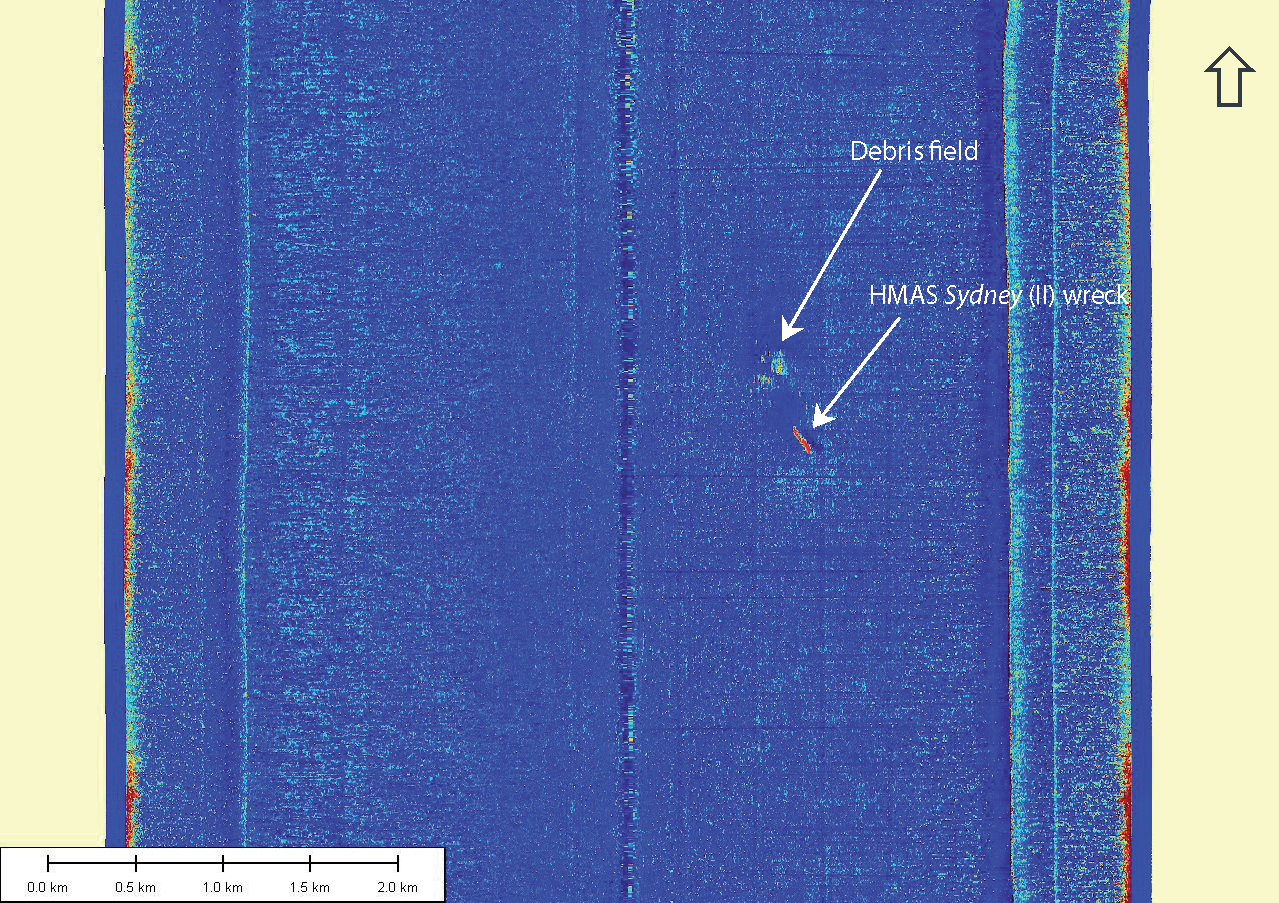
A full 6km swath sonar image showing the location of the Sydney wreck site on the starboard sonar channel is provided in Figure 3-1. The red colour of the sonar target is indicative of an acoustically strong, hard contact. Another indicator that this was the wreck site was the anomalous nature of the sonar contact relative to the surrounding seabed, which is featureless and of low acoustic reflectivity.
After finding the wreck site a number of high resolution and reduced swath investigation lines using the SM-30 and AMS-60 sonar systems were run in order to confirm that the sonar target was Sydney. Investigative parameters included target length and width and any salient structural features typical of the cruiser.
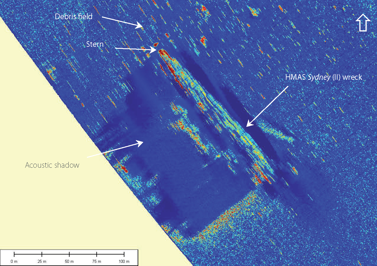
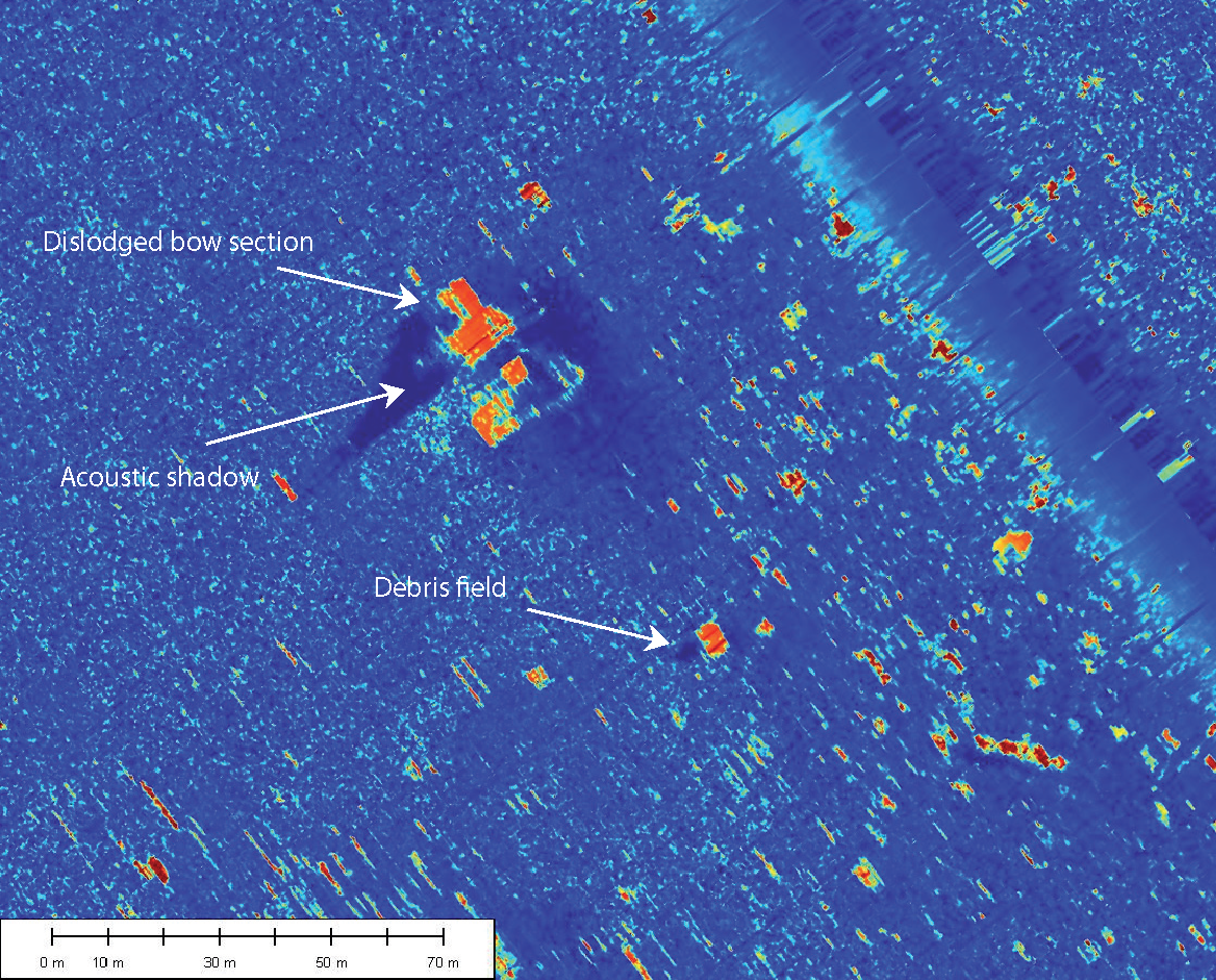
Interpreted main wreck length and width values determined from sonar images are 166m and 18m respectively. Dimensions of the interpreted dislodged bow section are approximately 28m long and 14m wide. Acoustic shadowing observed on the sonar images revealed a maximum main wreck height of approximately 14m, and bow section height of 10.5m above the surrounding seabed. These dimensions correlate well to those of Sydney.
Two enlarged high resolution AMS-60, 600m swath sonar images showing the main wreck and dislodged bow section are presented in Figures 3-2 and 3-3 respectively.
ROV Inspection
An ROV inspection of the Sydney wreck site provided visual confirmation of the wreck. High quality still photographic and video imaging confirmed the nature of the sonar targets, including not only the main wreck but also the numerous items of debris and wreckage within the debris field to the NNW.
A summary of the Sydney dive program and approximate water depth at each location is provided in Table 3-2.
| Dive Location | Date | Dive No. | Approx. Water Depth |
|---|---|---|---|
| HMAS Sydney (II) wreck | Dive 1 | 2410m | |
| HMAS Sydney (II) wreck | Dive 2 | 2480m | |
| HMAS Sydney (II) debris field NNW of wreck | to | Dive 3 | 2220m |
| HMAS Sydney (II) debris field | Dive 7 | 2220m | |
| HMAS Sydney (II) wreck | Dive 7 | 2430m |
ROV inspection Dive 1, Dive 2 and the latter part of Dive 7 concentrated on the main wreck section. Dive 1 was generally unsuccessful as the ROV was unable to exit the TMS garage and was therefore vulnerable to surface vessel movement. This resulted in blurred photographs and the inability of the ROV to approach the wreck safely. This dive was eventually aborted and superseded by Dive 2.
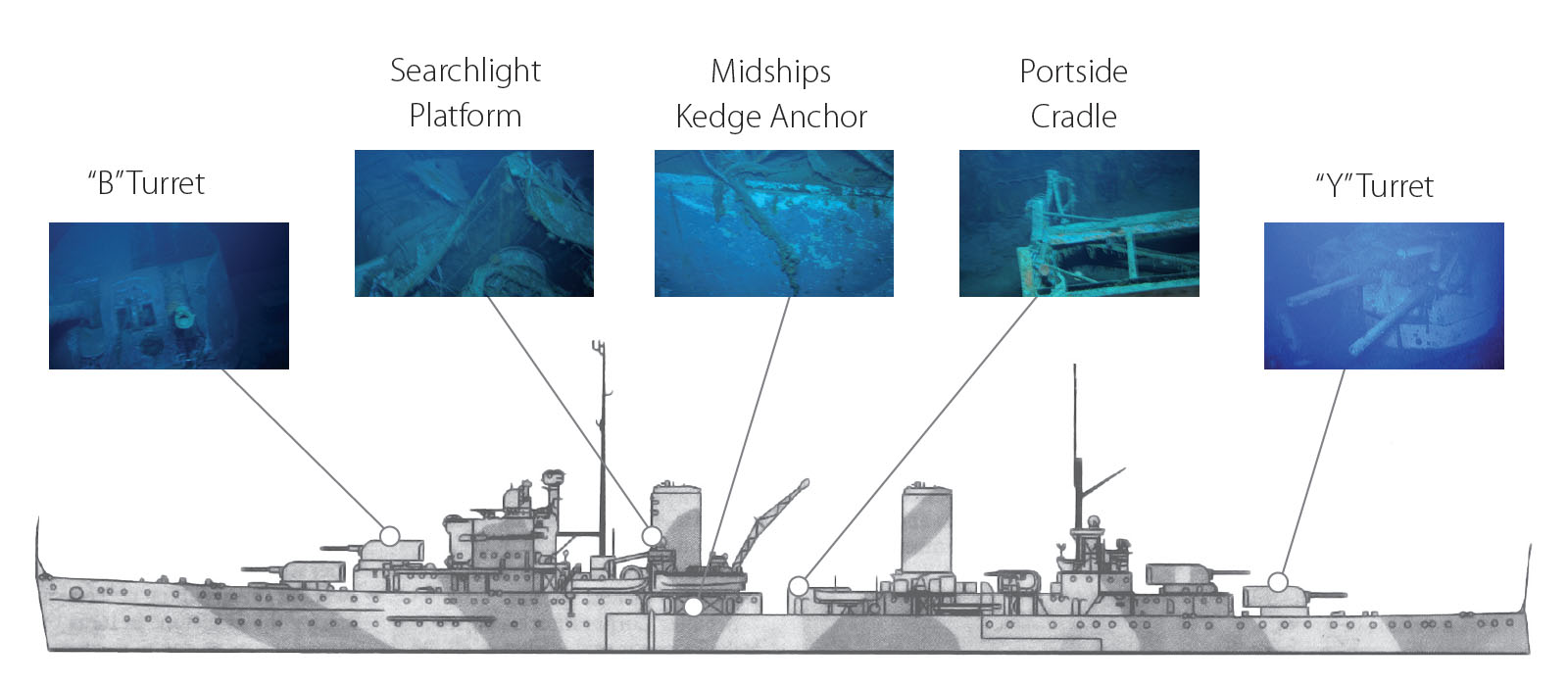
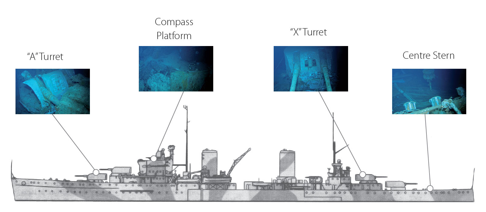
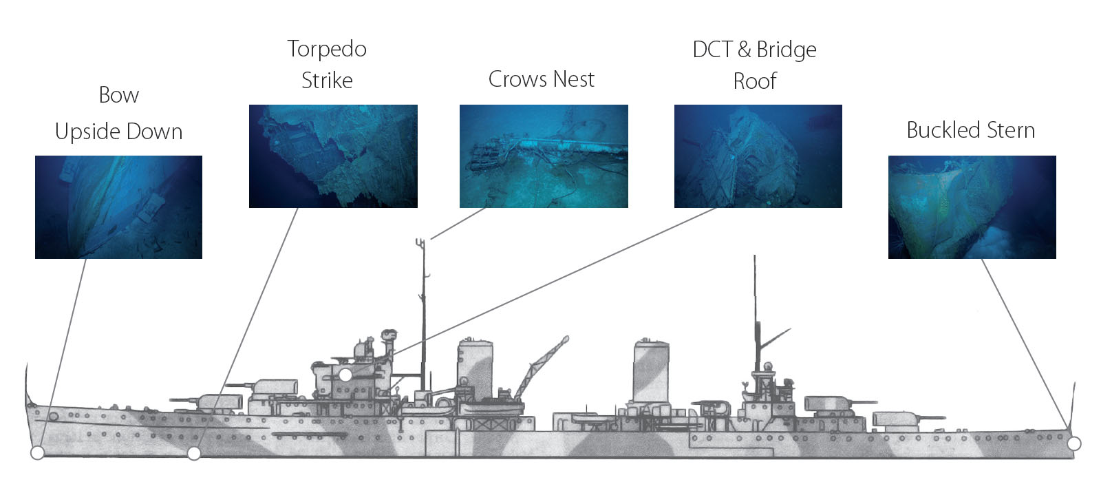
Three Sydney ROV photo location guides from photos acquired during Dive 2 and Dive 7 are presented in Figures 3-4 to 3-6.
ROV inspection Dive 3 and the initial part of Dive 7 were undertaken within the debris field that extends generally NNW from the main wreck. These ROV dives were based primarily on repositioned sonar target data.
A number of large sonar targets were identified within the debris field and although these formed the basis of the respective dive plans, numerous items of both identifiable and unidentifiable debris and wreckage were also observed while the ROV was transiting between them.
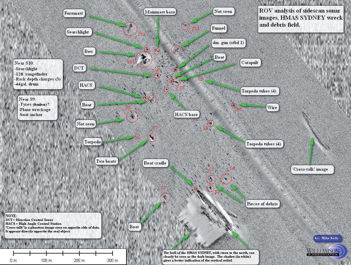
The description and position of some of the largest targets identified within the debris field are provided in Table 3-3. An AMS-60, 600m swath sonar image showing the position and description of salient items identified during the ROV inspection of the debris field is provided as Figure 3-7.
| Sonar Target No. | Description based on ROV inspection | Latitude (S) | Longitude (E) |
|---|---|---|---|
| S1 | 27-ft whaler boat | ||
| S2 | Large piece of unidentified debris | ||
| S3 | Large piece of unidentified debris | ||
| S4 | Large piece of unidentified debris | ||
| S5 | Large drum and wire used for berthing | ||
| S6 | Torpedo tubes | ||
| S7 | Boat lying across what is believed to be 36 ft motor pinnace | ||
| S8 | (Not found) | ||
| S9 | Aeroplane catapult and adjacent boat | ||
| S10 | Direction control tower and bridge roof | ||
| S11 | Dislodged bow section | ||
| S12 | Foremast | ||
| S13 | (Not Found) |
HSK Kormoran wreck Site
The following contains excerpts from Section 3.3 of the Final Report.
Refer to Appendix H2, Drawing No. 27098-001 and 27098-003:
- Appendix H2 - Drawing No. 27098-001 - HMAS Sydney (II) and HSK Kormoran Wreck Location (in PDF format)
- Appendix H2 - Drawing No. 27098-003 - HSK Kormoran Wreck location (in PDF format)
Side Scan Sonar Survey
The Kormoran wreck site was identified along Line 9, on 6km swath SM-30 side scan sonar data at () on .
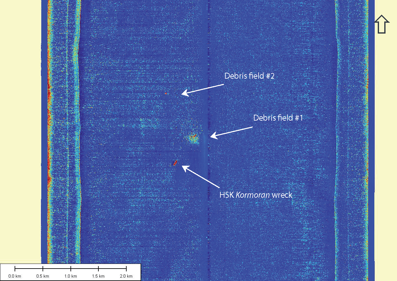
Sonar data showed one large section of superstructure lying upright and orientated generally SSW/NNE with the bow to the north, an extensive debris field (debris field #1) approximately 500m to the north east containing another large section of intact superstructure, and a smaller debris field (debris field #2) approximately 1.3km to the north.
Key wreck site coordinates are provided in Table 3-4.
| Location | Latitude (S) | Longitude (E) |
|---|---|---|
| HSK Kormoran wreck – centre of superstructure | 26° 06′ 32″ | 111° 04′ 21″ |
| HSK Kormoran wreck – centre of large piece of superstructure within extensive debris field #1 | 26° 05′ 46″ | 111° 04′ 33″ |
| HSK Kormoran wreck – centre of largest piece of wreckage within northernmost debris field #2 | 26° 05′ 23″ | 111° 04′ 15″ |
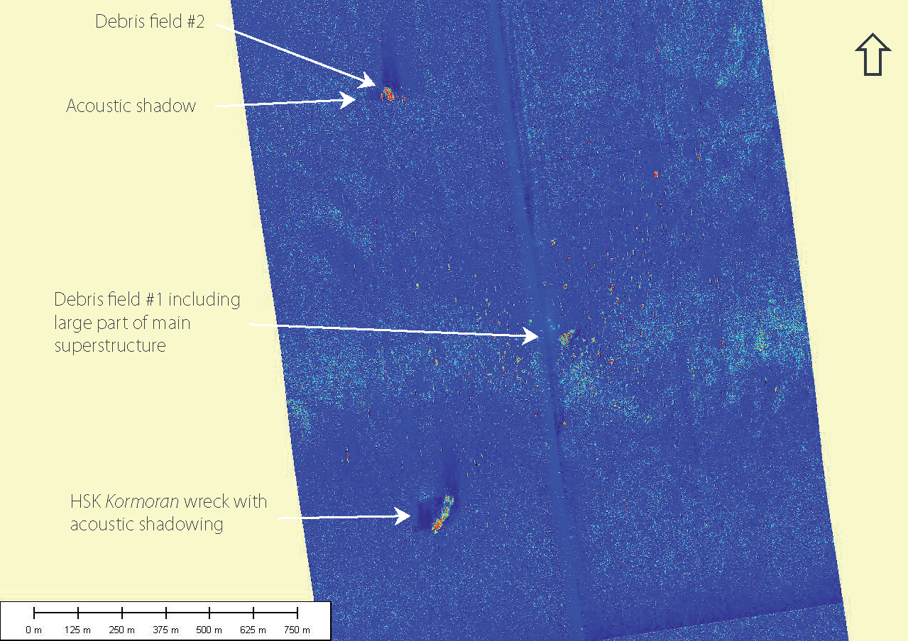
Full 6km and 1.5km swath sonar images of the Kormoran wreck site on the port sonar channel are shown in Figures 3-8 and 3-9. The red colour of the sonar targets is indicative of acoustically strong, hard contacts. As with the Sydney wreck site, this wreck site exhibited anomalous sonar returns relative to the surrounding featureless seabed.
A number of high resolution and reduced swath investigation lines using the SM-30 and AMS-60 sonar systems were run in order to the confirm that this was the Kormoran.
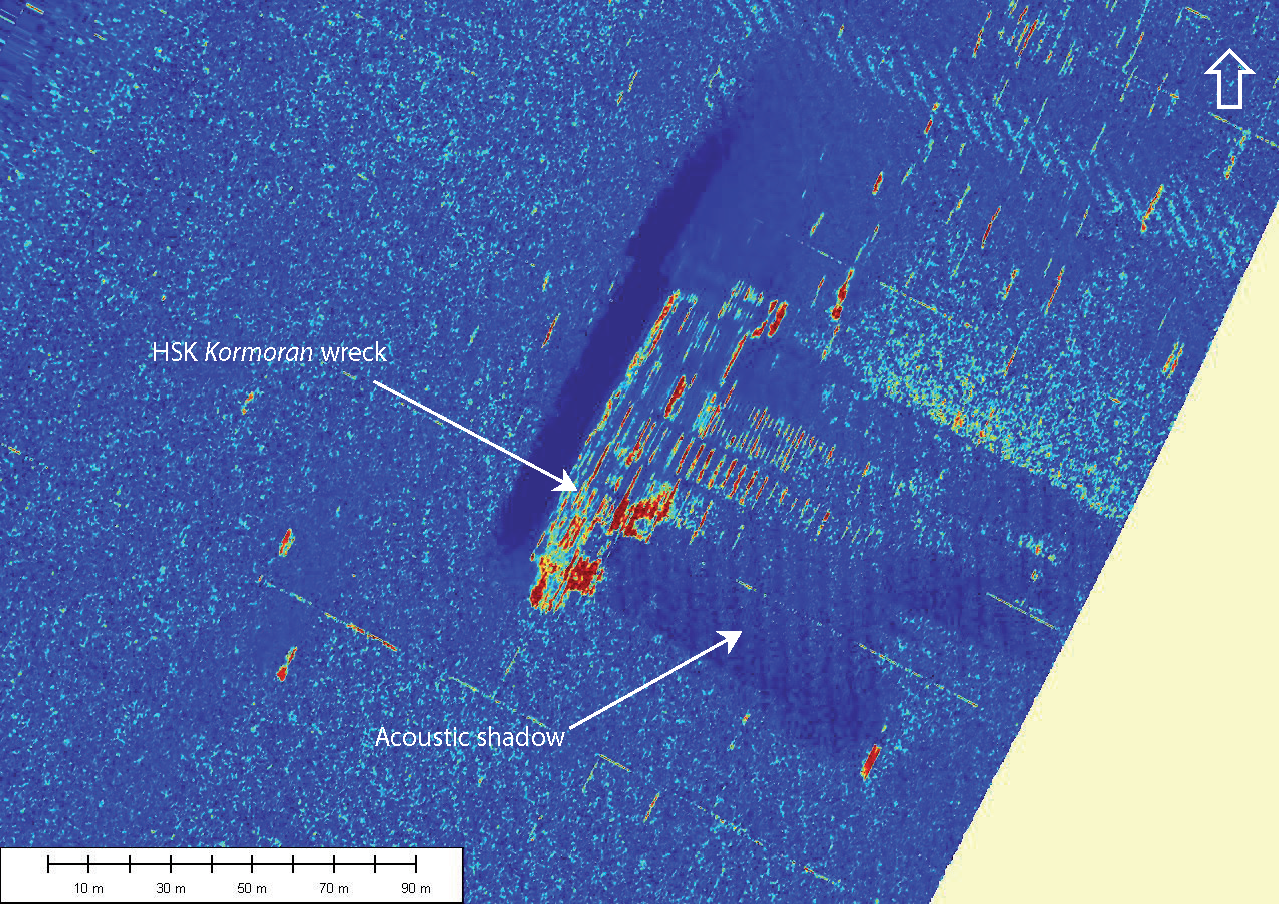
The main section of superstructure to the south is approximately 90m long, 20m wide and up to 20m high, as determined from the sonar images. These dimensions correlated to known dimensions between the midships accommodation and the bow, and were later confirmed by ROV inspection. An enlarged high resolution AMS-60, 600m swath sonar image of the main wreckage is provided as Figure 3-10.
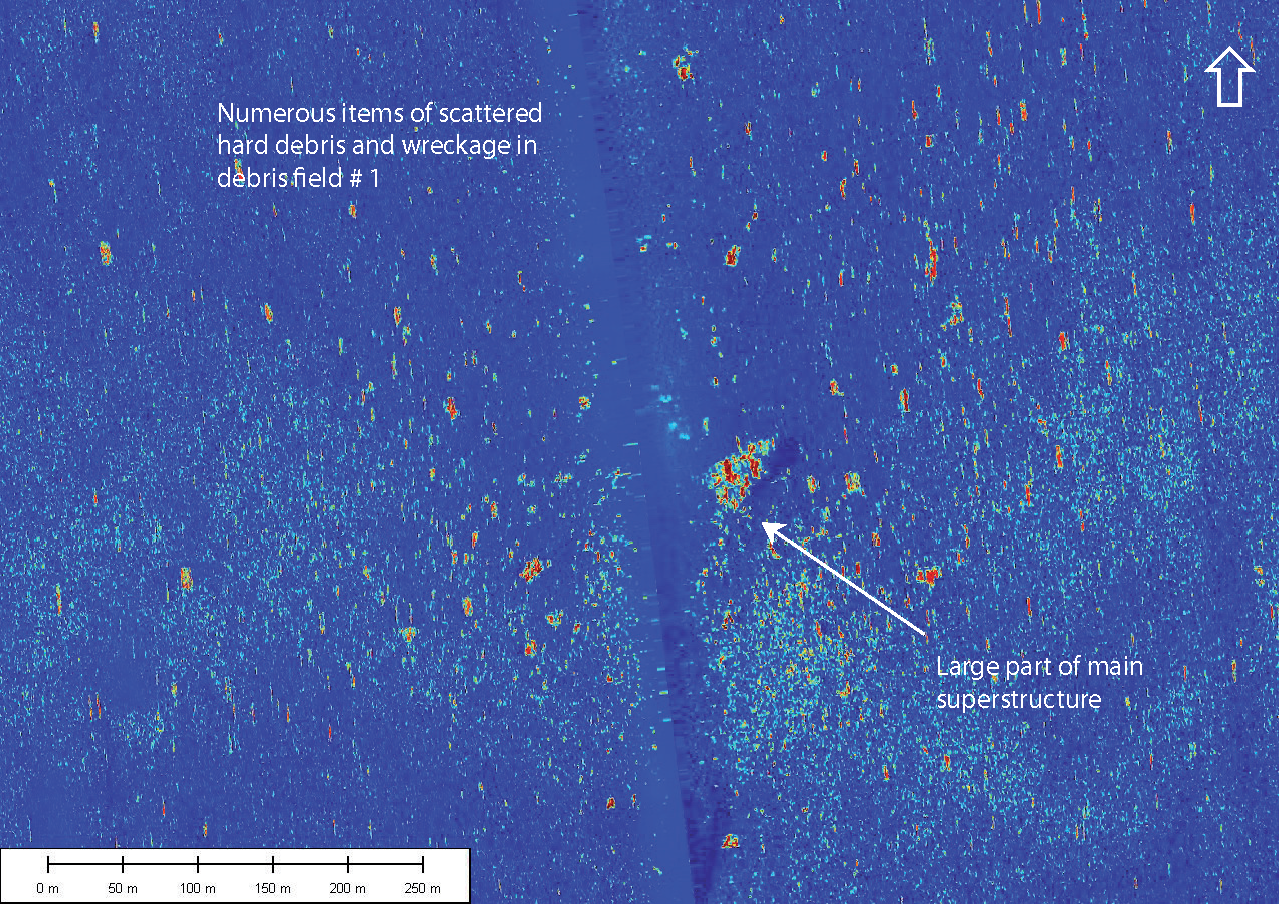
Debris field #1 to the north east is extensive, measuring nearly 1km across and is centred on a large piece of superstructure approximately 50m long, 20m wide and 15m high. An enlarged high resolution AMS-30, 1.5km swath sonar image of debris field #1 is provided as Figure 3-11.
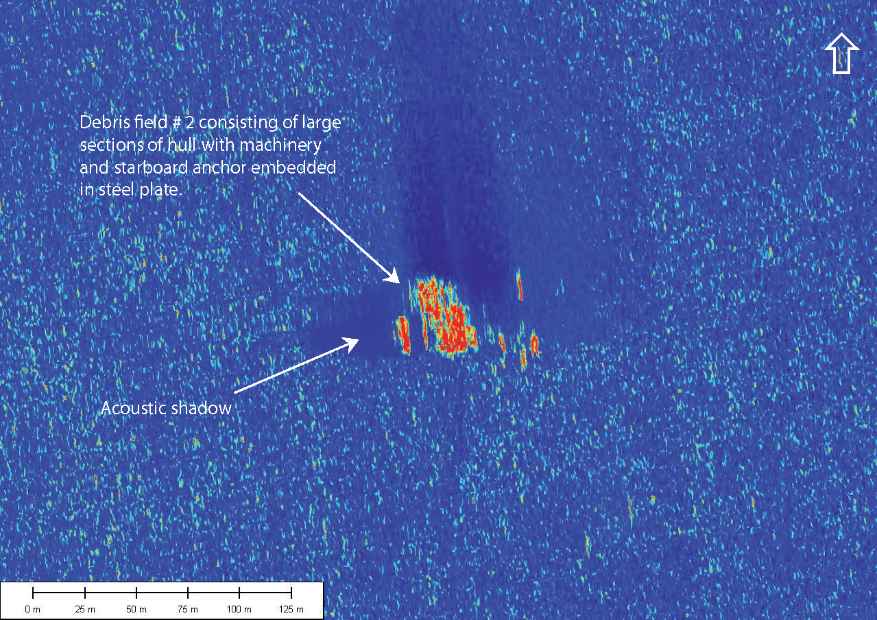
Debris field #2 contains only a few sonar targets, the largest measuring approximately 35m long, 15m wide and 15m. A high resolution AMS-30, 1.5km swath sonar image acquired over debris field #2 is presented as Figure 3-12.
ROV Inspection
An ROV inspection of the Kormoran wreck site provided visual confirmation of the wreck. High quality still photographic and video imaging confirmed the nature of some of the largest sonar targets. Due to time constraints, ROV inspection concentrated on the main wreck section with some time spent investigating the largest items of wreckage identified on the sonar within each of the two debris fields.
A summary of the Kormoran dive program and approximate water depth at each location is provided in Table 3-5.
| Dive Location | Date | Dive No. | Approximate Water Depth |
|---|---|---|---|
| HSK Kormoran wreck | Dive 5 | 2580m | |
| HSK Kormoran debris field #1 | Dive 6 | 2583m | |
| HSK Kormoran debris field #2 | Dive 6 | 2602m |
The wreck of the Kormoran was positively identified during ROV inspection Dive 5. However, the dive was aborted because a jammed manipulator arm prevented the ROV from exiting the TMS garage. Video footage was acquired but no still photographs were taken due to excessive movement of the ROV and TMS unit.
Dive 6 was undertaken in three parts: inspection of the largest section of wreckage followed by an inspection of each of the largest pieces of wreckage within debris fields #1 and #2.
Inspection of the forward section of the wreck confirmed that the vessel had broken near the aft of the main accommodation block. Inspection of the largest item of wreckage within debris field #1 revealed another large section of the superstructure surrounded by numerous items of wreckage. The height of this section was confirmed during the inspection.
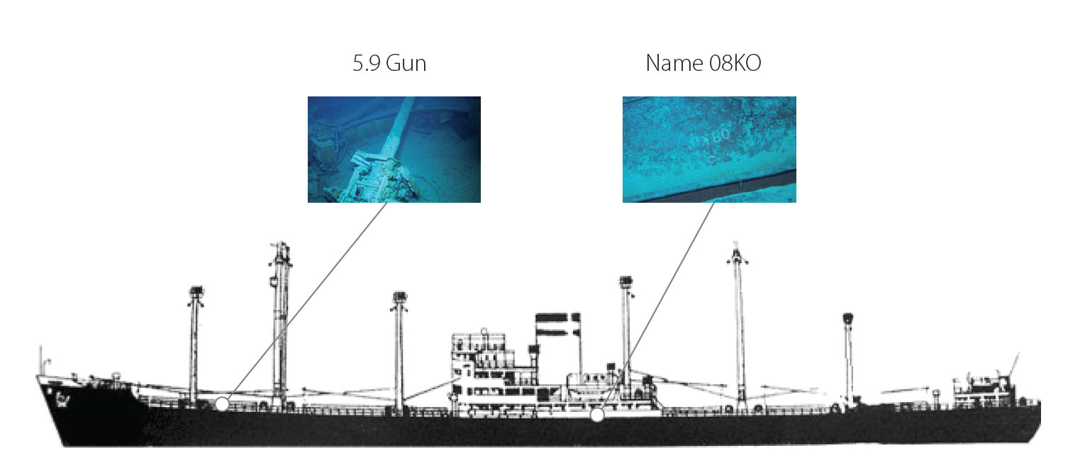
Finally, inspection of the smaller debris field #2 to the north revealed the largest item of debris to be a large section of the port midships and included what appeared to be machinery or main engine block, with lettering reading "08KO" found on plating just above the bilge keel. The lettering is consistent with that found on Kormoran ship's drawings.
A Kormoran ROV photo location guide from photos acquired during Dive 6 is presented in Figure 3-13.